KF Components, ISO-K Components and ISO-F Components

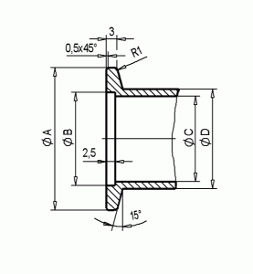
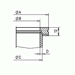
The components are dimensioned to German DIN 28403 standards and the product lists dimensions for the various DN sizes are standard. They are on the chart on this page. Other dimensions are shown with diagrams for each component.

DN KF
Type

A
mm

B
mm

C
mm

D
mm

E
mm
No of Lugs
kf flange DN 10
30
12.2
10
14
48
2
DN 16
30
17.2
16
20
48
2
DN 20
40
17
21
25
2
DN 25
40
26.2
24
28
58
2
DN 32
55
34
34
38
DN 40
55
41.2
40.5
44.5
73
4
DN 50
75
52.4
51
57
93
4
DN 60
75
62
60
64
4
             
ISO-K & ISO-F
Type

A
mm

B
mm

C
mm

D
mm

E
mm
No of Lugs
iso flange DN 63
95
70
76.1
3.2
130
4
DN 100
130
102
108
3.2
165
8
DN160
180
153
159
3.2
225
8
DN200
240
213
219
3.2
285
12
DN250
290
261
273
3.2
335
12
DN320
370
318
324
3.2
425
12
DN400
450
400
406
3.2
510
16
DN500
550
501
508
3.2
610
16
DN630
690
630
660
3.2
750
20
             
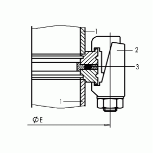
Flange connections High vacuum tight connection of two flanges is achieved by inserting a seal (centering ring and O-ring).
iso-k flange Clamp Flange to Clamp Flange Connection with clamps and screws which fit to the groove of the clamped
flanges.
1 Clamp Flange
2 Clamp Bolt
3 Seal
 
 
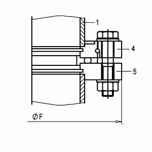
iso-f flange Clamp flange to rigid flange For this connection an overthrow flange with retaining ring is used.
The retaining ring is pressed into the outer groove of the clamped flange thus fixing the overthrow flange to the clamped flange. The holes are lined up with the opposite rigid flange. Both flanges are bolted together.
1 Clamp Flange
2 Overthrow Flange
5 Locking Flange
 
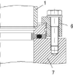
iso flange Clamped flange to base blate Claws which fit in the groove of the clamped flange and bolts are used for this connection.
1 Clamp Flange
6 Locking Flange
7 Threaded Base Plate